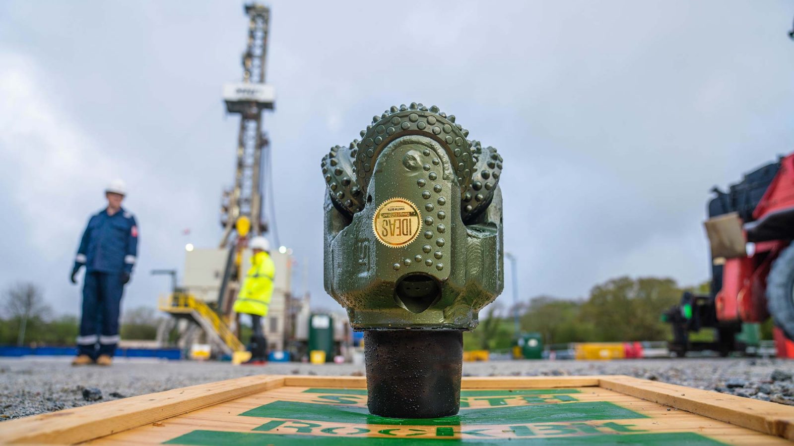
The rig we used to drill deep into the granite beneath the Eden Project was a Bentec 450 Eurorig, owned and operated by Czech company MND.
At 55m high, and with a 450-tonne hook load capacity, it was bigger than any UK-based land rig. It had to be big and powerful because in a very deep well (like EG-1) the drillstring is long and heavy in the lower sections.
The Bentec 450 Eurorig
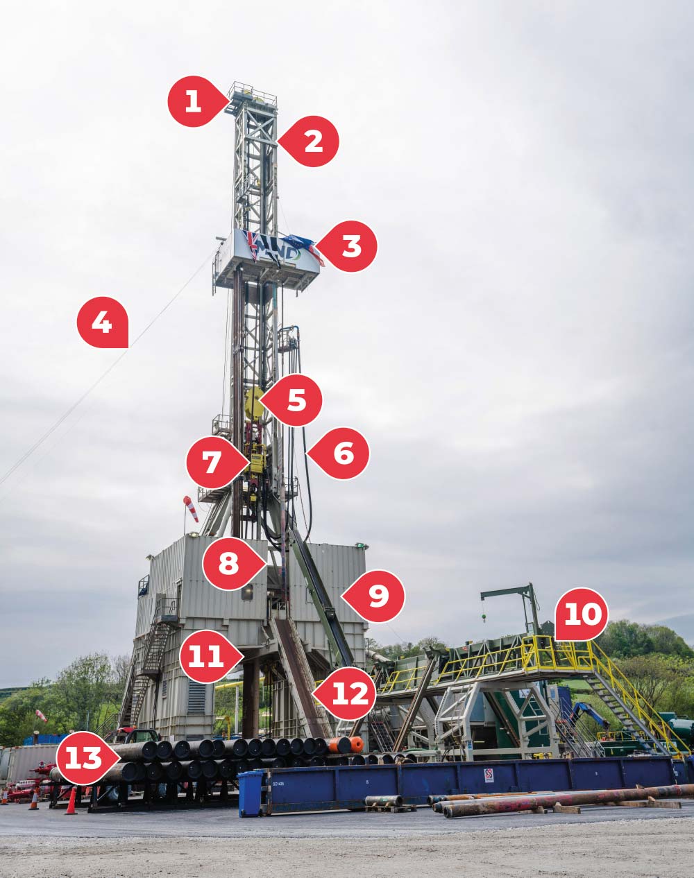
1 – Crown Block – The set of pulleys at the top of the derrick (mast), over which the drilling line is threaded.
2 – Mast or Derrick – The steel framework / structure used to support the crown block and the drillstring. So-called because it looks like a gallows designed by Thomas Derrick, a 16th century executioner who hanged over 3000 people!
3 – Monkey Board or Fingerboard – A working platform part way up the derrick in which the derrickman stores drillpipe when “tripping in or out” of the hole. The drillpipe is ‘racked’ in slots between steel fingers ready for use. Each joint of drillpipe is 9m long and is connected to two others to make a ‘stand’ of three before tripping in, to save time.
4 – Geronimo Line – This super-steep zip wire is a safety feature. Running from the monkey board to an anchor point on the ground, a short distance from the rig, it’s a rapid escape line for the derrickman in an emergency. The derrickman would disconnect their safety belt from the rig, rehook it over the Geronimo line, firmly grip the handle and – “Geronimo!” – ride down. (Thankfully, there’s a handbrake to slow the descent.) The name is a reference the 1940s US paratroopers, who first coined the term ‘Geronimo’ as a jumping cry.
5 – Travelling Block – The set of pulleys that move up and down in the derrick. A wire rope is threaded through them and up to the crown block on the top of the derrick. The pulley system allows heavy loads (drillstring & casing) to be lifted out of or lowered into the wellbore.
6 – Kelly Hose – A large-diameter, high-pressure flexible pipe which connects the standpipe to the topdrive. It’s an essential piece of kit because it allows the topdrive (and with it the drillstring and bit) to move up and down while drilling fluid is being pumped through the drillstring.
7 – Topdrive – This turns the drillstring and allows drilling fluid to be pumped through it. The topdrive is suspended from the travelling block, so the rotary mechanism is free to travel up and down the derrick.
8 – Vee Door – A V-shaped opening in one side of the derrick that enables long pipes and tools to be lifted inside the derrick. It’s positioned to line up with the slide and catwalk.
9 – Drillfloor – The main (but fairly small) area in which the rig crew works, and where drillpipe is added to or removed from the drillstring. The rig floor is the most dangerous area on the rig because heavy equipment and components are moved around there. The doghouse – a combined control room and office used by the driller and crew – is next to the drill floor, behind the screening on this image.
10 – Catwalk (Pick-up/Lay-down Machine) – A long, rectangular platform which sits at a right angle to the vee-door, at the bottom of the slide. It’s used to line up drilling components in preparation for picking them up from /laying them down on the drillfloor.
11 – Bell Nipple – A wide pipe at the top of a casing string that serves as a funnel to guide drilling tools into the top of the well.
12 – Slide – Slipway used to load drilling components onto and off the rig floor.
13 – Casing Joints – Individual pieces of large-diameter steel pipe which are connected together and lowered into the wellbore, where they’re cemented in place to form a liner. Casing is designed to withstand a variety of forces, such as collapse, burst, tensile failure and corrosion. It comes in different sizes to fit the different diameter sections of the well. In EG-1, the widest ‘surface’ casing is 20” in diameter, reducing to 9 ⅝” ‘production’ casing between 1500m and 4000m.
A technical rig data-sheet is available for download here:
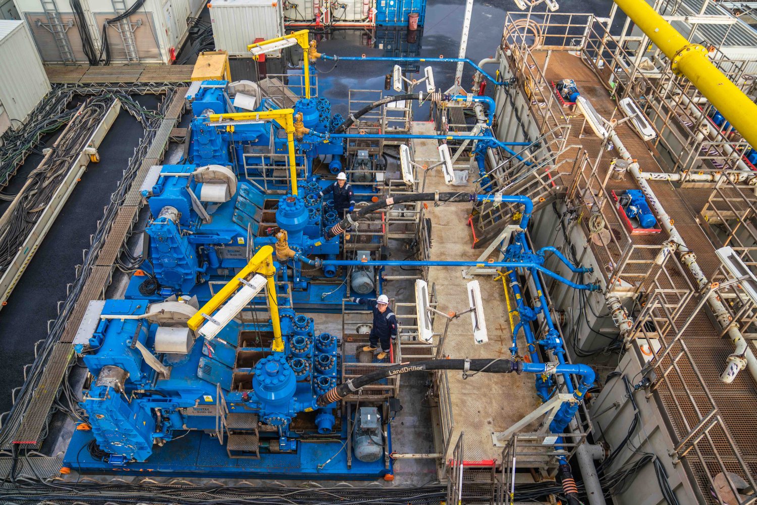
Around the rig
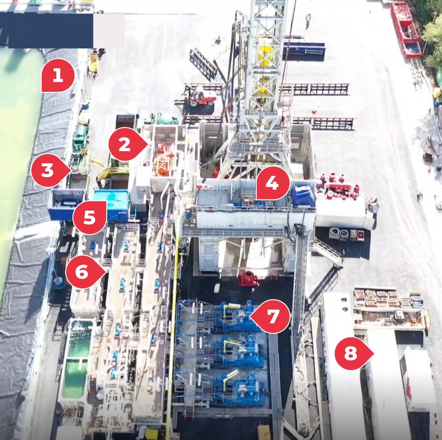
1 – Lagoon – The Eden lagoon is a large (3,200m3) water storage facility, mainly used after drilling, when we were testing the well. We tested the rate at which the well was able to produce hot water (production tests) – so the lagoon needed to be big enough to hold the maximum volumes we anticipated could be produced. And we also tested the rates at which water could be reinjected into the well, so it acted as our reservoir at this stage.
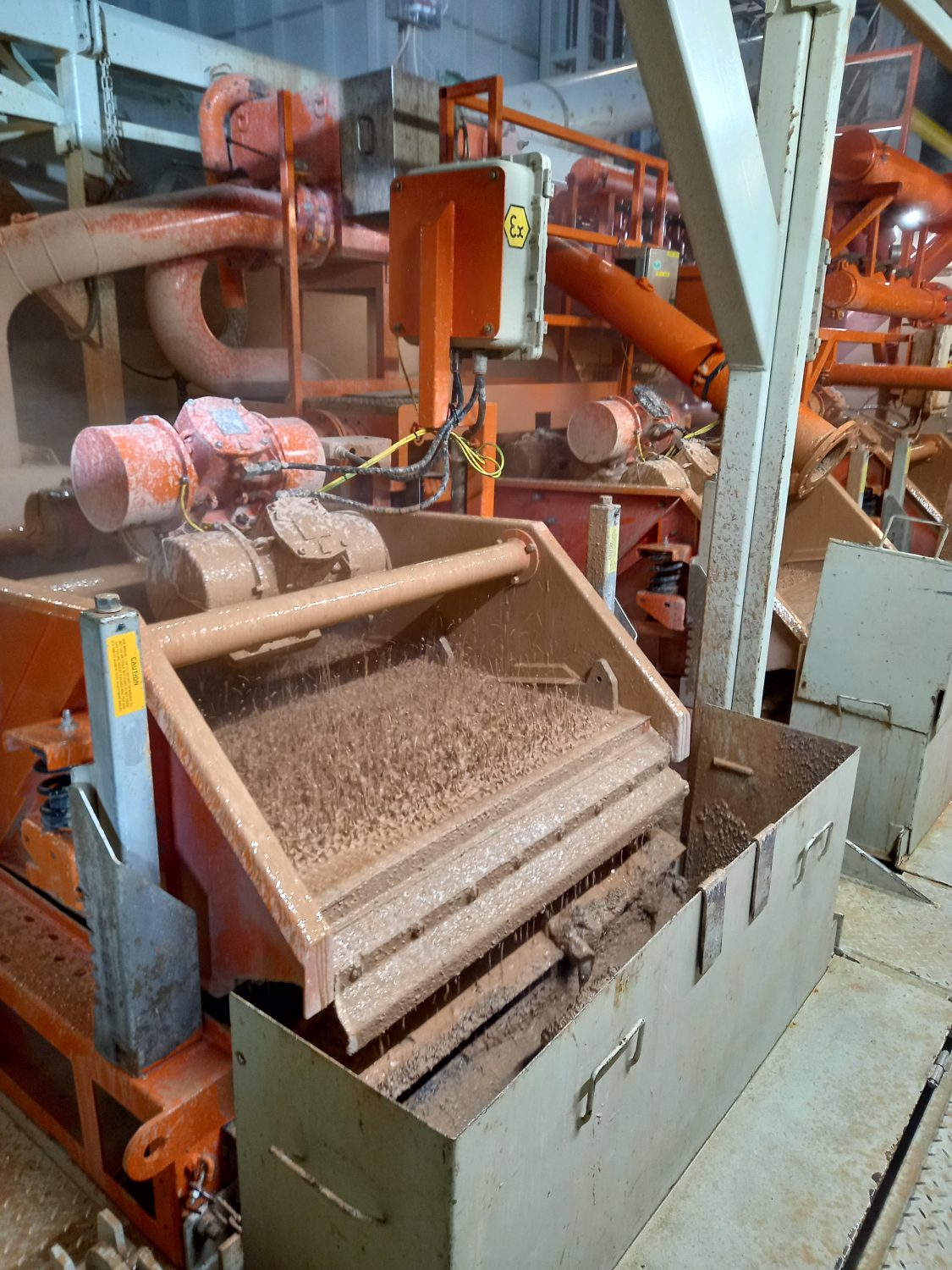
2 – Shale Shakers – As the drill bit cuts through the granite, small cuttings are transported to surface by the mud. The shale shakers vibrate mesh screens at a high frequency to sieve the cuttings out from the mud. We were then able to dispose of the cuttings and re-use the mud, pumping it down hole again.
3 – Waste Management System – All cuttings from downhole were processed to remove and reuse as much of the drilling fluid as possible.
4 – Drawworks – A large, winch-like system used to lower and raise the travelling block and topdrive during drilling.
5 – Centrifuge Pumps – These formed part of the waste management system and removed the finer particles of granite from the drilling fluid.
6 – Mud Pits – The tankers or “pits” were used to mix and store drilling fluid or “mud”.
7 – Mud Pumps – These pumps weighed a whopping 42 tonnes each. They pumped the mud at very high pressure down the centre of the drillstring, through the bit and back to surface via the annulus (the space between the drillpipe and the side of the well).
8 – Generators – The rig provided its own power using four diesel generators. In other locations, where a suitable power source is available, an electrified rig could be used.
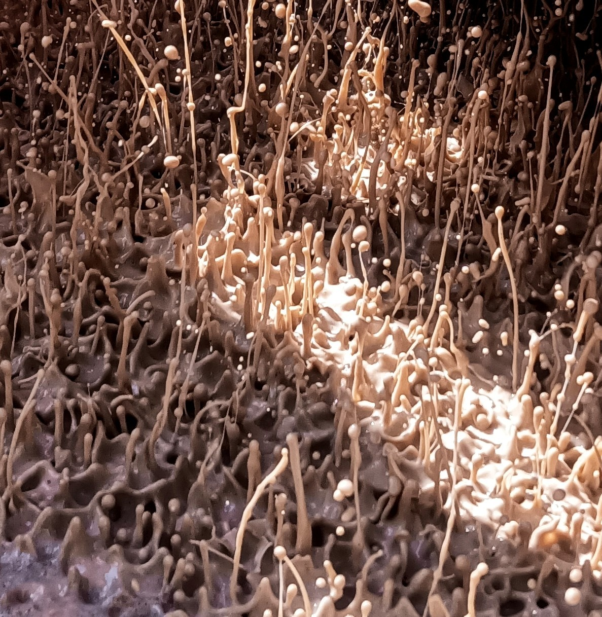
So, what is ‘mud’?
Mud, or drilling fluid, is used to cool and lubricate the drill bit (which would otherwise get very hot with friction) and to bring the cuttings – the rock which has been bored out – to the surface. Its consistency is a bit like ketchup, and it’s made up of things like natural bentonite clay (as used in cosmetics and cat litter) and xantham gum (a starch used in foods). It’s pumped down through the centre of the drillpipe and out through nozzles in the drillbit, before picking up the cuttings and transporting them to the surface via the annulus – the space between the drillpipe and the side of the well.